


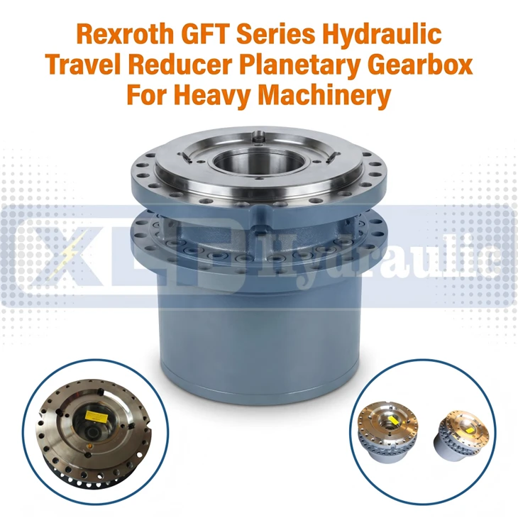
Rexroth GFT Series Hydraulic Travel Reducer Planetary Gearbox For Heavy Machinery
Wuhan Xinlaifu Hydraulic Equipment Co., Ltd. is one of the leading manufacturers and suppliers of rexroth gft series hydraulic travel reducer planetary gearbox for heavy machinery in China. With abundant experience, we warmly welcome you to buy high quality customized products at competitive price from our factory. Also, OEM&ODM service is available.
Specifications
")
| Type | GFT Series Planetary Reducer |
| Brand | XLF Hydraulic |
| Max Output Torque Range | 9500–450000 Nm |
| Rated Working Pressure | 35 MPa (350 bar) |
| Peak Pressure | Max 40 MPa (400 bar) |
| Mount Flange | SAE Standard Flange |
| Port Size | SAE Standard Ports |
| Built-in Parts | Integrated Parking Brake & Seals |
| Recommended Oil | ISO VG 220 Industrial Gear Oil |
Product Overview
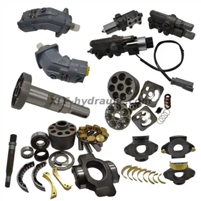
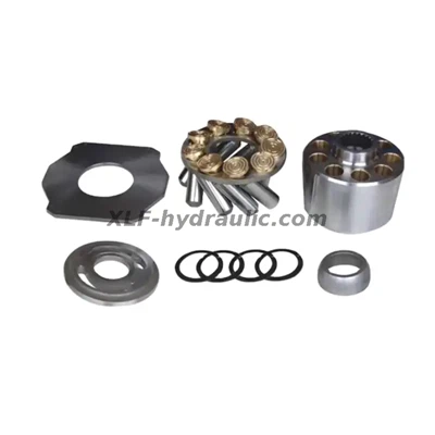
Models GFT 0009T2, GFT 0013T2, GFT 0017 T2/T3, GFT 0050 T3, GFT 0080 T3, GFT 0220 T3/R3 and GFT 0330 T3/T4 are heavy-duty hydraulic planetary reducers with 2/3/4-stage transmission structures, belonging to the GFT Series. Custom configuration and production coding are available to support diverse specification variants, including different gear stages, gear ratios, output forms, parking brake setups and sealing solutions. Adopting high-precision planetary drive technology and premium hardened gear teeth plus inner gear rings that guarantee reliable operation under high torque and harsh load conditions, these reducers serve as direct aftermarket replacements for original OEM reducers with fully matched installation dimensions and interface parameters.
The GFT Series represents premium high-efficiency planetary reducers, delivering stable high-torque output under a compact, space-saving casing. The matched hydraulic system features a standard working pressure of 350 bar, fully adapting to long-duration heavy-load operation. Deployed in severe service environments including open-pit mining, construction lifting, road paving, concrete works and agricultural operations, these reducers exhibit excellent load resistance and long-term operational durability. They act as the core hydraulic drive components for heavy-duty machinery such as excavators, crawler cranes, road rollers, pavers, mining equipment, agricultural machinery and marine & offshore lifting facilities. Designed with standard SAE heavy-duty mounting flanges and spline connections, plus a reinforced integral housing structure, the entire series resists frequent heavy shock loads and continuous mechanical vibration, perfectly fitting the harsh operating conditions of various mobile and industrial hydraulic equipment.
This reducer range supports a wide variety of customized structural variants, including tailored gear stages, special output shafts and spline profiles purpose-built to pair with different types of hydraulic motors and integrated hydraulic transmission assemblies. Custom versions can be engineered to remove conventional intermediate connecting components, enabling direct assembly with matched hydraulic drive systems via dedicated spline and interface designs. They are ideal for hydraulic drive systems with limited installation space, or equipment adopting integrated modular and lightweight design concepts, including electro-hydraulic power module applications in electrified construction machinery.
Core Advantages
1. Integrated Structure Design - An Ideal Choice For Integrated Drive & Electrified Systems
GFT Series Planetary Hydraulic Reducer adopts optimized integrated structure design, which is a dedicated configuration for integrated drive and electrified hydraulic systems:
Integrated connecting structure: Custom spline and shaft end design are adopted. External radial loads are shared by the matching hydraulic motor assembly on the user's equipment; Direct integration with hydraulic motors & drive assemblies: The reducer can be directly flange-mounted to various fixed / variable displacement hydraulic motors without additional support bearings or couplings, perfectly matching the electro-hydraulic power module; Compact overall dimension: The streamlined multi-stage planetary structure greatly shortens the overall installation size, making it particularly suitable for equipment with extremely limited installation space; Easy installation: Standard SAE heavy-duty mounting dimensions and multi-bolt fixed flange layout enable seamless matching with user equipment and ensure excellent concentricity during operation. Besides, the modular integrated design supports multiple reducers tandem installation, further expanding system configuration flexibility.
2. GFT Series - High Performance Planetary Hydraulic Reducer
The GFT Series stands for premium high-performance planetary hydraulic reducers in the product lineup:
High torque density: Delivers stable high torque output within a compact housing. The matched hydraulic system features a standard continuous working pressure of 350 bar for all models; Advanced planetary gear & housing assembly: Equipped with optimized 2/3/4-stage planetary transmission and reinforced hardened gear teeth & inner gear ring structure, it achieves higher mechanical efficiency and strong resistance to shock and vibration; High-stability gear meshing & sealing technology: Precisely machined gear sets maintain stable meshing performance with automatic wear compensation, keeps excellent transmission efficiency during long-term operation and effectively reduces power loss; Harsh condition adaptability: Capable of working stably under rated continuous pressure and long-duration heavy load, adapting to a wide temperature range (-20°C ~ +45°C) and frequent load changes. It performs reliably on construction, mining, marine, road and agricultural machinery under severe working conditions such as dust, salt spray and heavy vibration.


Q: What are the differences between GFT, GFT-N and GFT-W series? Which equipment are they suitable for?
A: GFT and GFT-N are travel reducers with outer rotating housing, specially designed for the travel drive of tracked equipment, such as excavators, crawler cranes, road rollers, pavers, mining tracked vehicles and agricultural tracked machinery. GFT-W is a winch reducer adopting an internal drum compact structure for winch mechanisms, widely used for truck cranes, port cranes, marine deck winches, offshore platform equipment and drilling rigs.
Q: Can GFT series be used as direct replacement for original imported reducers? Are the dimensions fully matched?
A: Yes, it can serve as a direct aftermarket replacement for original imported reducers of the same specifications. All mainstream models adopt 1:1 matching on overall dimensions, mounting flanges, bolt holes and spline parameters. No modification on equipment is required, which enables easy assembly and disassembly for equipment maintenance.
Q: Which types of hydraulic motors can be matched with GFT reducers? Is flange connection available?
A: This series is compatible with multiple fixed and variable displacement hydraulic motors including A2FE, A6VE, A10VE, A6VM and A2FM. Equipped with standard SAE flange interfaces, it can be directly flange-mounted with hydraulic motors without additional couplings or support bearings.
Q: Does the GFT series come with multi-disc parking brake? How to calculate the brake torque?
A: Most models are equipped with or optional multi-disc parking brakes (only for static braking, not for dynamic braking). The minimum brake torque of travel reducers equals 1 times the input torque; the minimum brake torque of GFT-W winch reducers equals 1.5 times the input torque.
Q: Can you customize gear ratio, mounting interface and other special specifications?
A: Full customization is available. We can adjust 2/3/4-stage transmission structure, gear ratio, output form, mounting holes, sealing configuration and brake parameters according to customer requirements, to adapt to various non-standard hydraulic transmission systems and integrated equipment.
Q: What lubricating oil is recommended for GFT reducers? What are the daily maintenance requirements?
A: We recommend 220# LS2 industrial gear oil or Great Wall L-CDK220 gear oil. For daily maintenance, just regularly check the oil level, fasten bolts and inspect abnormal noise. The first oil change is suggested after 150 hours of operation. Regular oil replacement is required under normal working conditions, and no complicated maintenance is needed.
Q: Why does the reducer leak oil? How to troubleshoot it?
A: Oil leakage is usually caused by loose bolts or aging seals. First, tighten all housing flange bolts completely. If the leakage persists, the sealing parts are worn. Please contact us to replace original seal kits, and do not disassemble the gear structure privately.
Q: What is the warranty period of GFT reducers?
A: We provide 12-month international warranty starting from the date of goods receipt. Within the warranty period, we offer free spare parts and technical support for product failures caused by non-human damage under normal working conditions. Damage caused by human error or improper use is not covered by the warranty.
Main Specifications
1. GFT Travel Reducer
1.1 General Model, Output Torque & Gear Ratio
| Model | Max Output Torque T2max (Nm) | Gear Ratio (i) |
|---|---|---|
| GFT 0009T2 | 9500 | 47.6 ~ 55.3 |
| GFT 0013T2 | 13000 | 32.1 ~ 37.6 |
| GFT 0017 T2 | 17000 | 45.4 ~ 54.0 |
| GFT 0017T3 | 17000 | 77.9 ~ 88.2 |
| GFT 0024 T3 | 24000 | 102.6 ~ 137.2 |
| GFT 0026T2 | 26000 | 50.5 ~ 62.0 |
| GFT 0034T2 | 34000 | 50.5 |
| GFT 0036T3 | 36000 | 115.0 ~ 138.8 |
| GFT 0040T2 | 40000 | 35.9 ~ 59.1 |
| GFT 0050T3 | 50000 | 73.9 ~ 125.7 |
| GFT 0060T3 | 60000 | 105.5 ~ 169.9 |
| GFT 0065T2 | 65000 | 55.4 |
| GFT 0080 T3 | 80000 | 99.0 ~ 215.0 |
| GFT 0110T3 | 110000 | 95.8 ~ 173.9 |
| GFT 0160T3 | 160000 | 210.8 ~ 251.0 |
| GFT 0220T3/R3 | 220000 | 97.7 ~ 365.0 |
| GFT 0330T3 | 330000 | 168.9 ~ 302.4 |
| GFT 0330 T4 | 330000 / 380000 | 451.7 ~ 826.6 |
| GFT 0450 T4 | 450000 | 347.1 ~ 421.7 |
1.2 Detailed Technical Parameters
Small & Medium Size Models
| Model | T2 max (Nm) | Gear Ratio (i) | Max Brake Torque TBr max (Nm) | Matched Hydraulic Motor |
|---|---|---|---|---|
| GFT 0013 T2 4000/1 | 13000 | - | - | A6VE 55 |
| - | 13000 | - | - | A2FE 45 |
| GFT 0017 T2 3000/1 | 17000 | 54.0 | 350 | A6VE 55 |
| - | 17000 | - | - | A10VE 63 / A2FE 45·63 |
| - | 17000 | 77.9 | 250 | A6VE 28 / A2FE 28 |
| - | 24000 | 102.6 ~ 120.5 ~ 137.2 | - | A6VE 55 |
| GFT 0024 T3 9000 | 24000 | - | 300 | - |
| - | - | 137.2 | 250 | - |
| - | - | - | - | A6VE 80 |
| - | - | 115.0 ~ 138.8 | - | - |
Medium & Large Size Models
| Model | T2 max (Nm) | Gear Ratio (i) | Max Brake Torque TBr max (Nm) | Matched Hydraulic Motor |
|---|---|---|---|---|
| GFT 0040 T3 9000 | - | - | 800 | - |
| GFT 0050 T3 1000/1 | 50000 | 84.2 ~ 91.1 | - | A6VE 80·107 |
| GFT 0050 T3 3000 | - | - | - | A6VE 80·107 |
| GFT 0050 T3 9000 SL·9000/1 | - | - | 800 | - |
| GFT 0050 T3 9000/2 | 50000 | - | 800 | A6VE 80 |
| GFT 0050 T3 9000/3 | - | - | - | A2FE 63 |
| GFT 0060 T3 7000/1 | - | - | 725 | A6VE 160 |
| GFT 0080 T3 1000·2000 | - | - | - | - |
| GFT 0110 T3 1000 | 110000 | - | - | - |
| GFT 0110 T3 9000 | - | - | - | A6VE 160 / A2FE 160 |
Extra Large Size Models
| Model | T2 max (Nm) | Gear Ratio (i) | Max Brake Torque TBr max (Nm) | Matched Hydraulic Motor |
|---|---|---|---|---|
| GFT 0160 T3 1000 | 160000 | 210.8 ~ 251.0 | 1020 | A2VE 107·160 / A2FE125 |
| GFT 0220 T3 9000/2 | 220000 | 97.7 | - | A6VM355 |
| GFT 0220 R3 9000/3 | 220000 | 145.4 | 1400 | A6VM 200 |
| GFT 0220 T3 9000/4 | 220000 | 365.0 | 1100 | A6VE160 |
| GFT 0330 T3 2000/3000 | 330000 | 268.9 ~ 252.0 ~ 302.4 | 2500 | A2FE 355 / A6VE250 |
| GFT 0330T4 1000 | 380000 | 826.6 | - | - |
| GFT 0330 T4 2000 | 330000 | 451.7 | 625 | A6VE160 |
| GFT 0450 T4 1000/1 | 450000 | 421.7 | 1450 | A6VE 250 |
| GFT 0450T4 1000/2 | 450000 | 347.1 | 1450 | A6VE 250 |
1.3 Overall Dimensions, Mounting Holes & Weight (Unit: mm / kg)
Medium Size Models
| Model | L1 | L2 | L3 | L4 | Mounting Holes | Weight (kg) |
|---|---|---|---|---|---|---|
| GFT 0050 T3 1000/2 | 270 | 310 | 350 | - | - | 145 |
| GFT 0050 T3 3000 | 270 | 370 | - | 400 / 400 | - | - |
| GFT 0050 T3 9000/2 | - | 370 | 408 | - | 16×M20 | 145 |
| GFT 0060 T3 7000/2 | - | - | 410 | - | 20×M20×1.5 | - |
| GFT 0080 T3 1000 | 420 | - | - | 550 | - | - |
| GFT 0080 T3 2000 | - | 430 | - | 520 | - | - |
Extra Large Size Flange & Interface Dimensions
| Model | D1 | D4 | D8 | Mounting Holes |
|---|---|---|---|---|
| GFT 0220 T3 9000/4 | - | 570 | 620 | 42×M30×2 |
| GFT 0330 T3 2000 | 680 | - | 785 | 30×M30 |
| GFT 0330 T3 3000 | - | - | - | 30×M30 |
| GFT 0450 T4 1000/2 | - | 680 | - | 36×M30×2 |
1.4 GFT 2160 Travel Reducer
Structure: 2-stage planetary gear mechanism, built-in swash plate piston motor
Configuration: Equipped with 2-speed motor with automatic shifting
Working Pressure: 350 bar
2. GFT-N Travel Reducer
2.1 Technical Parameters
| Model | Output Torque (Nm) | Gear Ratio (i) | Brake Torque (Nm) | Matched Hydraulic Motor |
|---|---|---|---|---|
| GFT 0600 N/1 | 600000 | 243.5 | 1×3115 | A2FM 500 |
| - | - | 289.1, 520.2 | 2×1830 | A2FE 160 / A6VM 250 |
| GFT 0800 N | 984000 | 284.8 | - | - |
| - | 1117000 | 401.5 | - | - |
| GFT 1300 N | - | 458.5 | 2×1700 | - |
2.2 Overall Dimensions & Weight (Unit: mm / kg)
| Model | D3 | D5 | D7 | L4 | Weight (kg) | Type Mark |
|---|---|---|---|---|---|---|
| GFT 0800 N | 779 | 885 | 1020 | 1332 | 5200 | ST |
| GFT 0800 N | 779 | - | - | 1211.5 | 3320 | CC |
3. GFT-W Winch Reducer
3.1 Basic Model Parameters
| Model | Max Output Torque (Nm) | Single Rope Pull (kN) | Gear Ratio (i) |
|---|---|---|---|
| GFT 0013 W2 | 19000 | 50 | 90.1 ~ 102.6 |
| GFT 0026 W2 | 26000 | 118 | - |
| GFT 0050 W3 | 42500 | - | - |
| GFT 0080 W3 | 67000 | - | - |
| - | 140000 | - | - |
| - | 200000 | - | 471 |
3.2 Detailed Technical Parameters
| Model | T2 max (Nm) | Single Rope Pull (kN) | Gear Ratio (i) | TBr max (Nm) | Matched Hydraulic Motor |
|---|---|---|---|---|---|
| GFT 0017 W2 4000 | 14000 | 67 | 45.4 | 460 | A6VE 55 / A2FE56·63 |
| GFT 0024W3 4000 | 19000 | 99 | 90.1 ~ 102.6 | 460 | A6VE55 / A2FE56·63 |
| GFT 0026 W2 2000 | 18000 | 84 | 62.0 | 710 | A6VE 80 / A2FE80·90 |
| GFT 0026W2 4000 | 18000 | 84 | 50.5 | 710 | A2FE 90 |
| GFT 0080 W3 6000/1 | 67000 | 231 | 61.3 ~ 79.1 | 1890 | A6VM160 / A2FM180 |
| GFT 0080 W3 6000/2 | 67000 | 231 | 61.3 ~ 79.1 | 1890 | A6VM 250 |
| GFT 0110 W3 4000 | - | - | 114.8 | - | - |
| - | - | - | 95.8 | - | A6VM 160 / A2FM 160·180 |
| - | - | - | - | - | A6VM 200·250 / A2FM 200 |
| GFT 0110 W3 9000 | - | - | - | - | A6VM 200·250 / A2FM 200 |
| GFT 0160 W3 4000 | - | - | - | - | - |
| - | - | - | - | - | A6VE 160 |
| GFT 0330 W3 9000/1 | 275000 | - | - | - | - |
| GFT 0330 W3 9000/2 | 275000 | - | - | 2×1700 | 2×A6VM 160 |
3.3 Overall Dimensions, Interface & Weight (Unit: mm / kg)
| Model | D1 | D2 | D3 | D4 | D5 | D6 | D8 | Dws | Weight (kg) |
|---|---|---|---|---|---|---|---|---|---|
| GFT 0017 W2 4000 | 250 | 290 | 320 | 14×M20 | 280 | 305 | 330 | 380 | 105 |
| GFT 0024 W3 4000 | 250 | 290 | 320 | 14×M20 | 280 | 305 | 330 | 385 | 130 |
| GFT 0026 W2 2000 | 270 | 310 | 350 | 16×M20 | 320 | 350 | 380 | 430 | 145 |
| GFT 0026 W2 4000 | 270 | 310 | 350 | 16×M20 | 320 | 350 | 380 | 430 | 145 |
| GFT 0080 W3 6000/1 | 380 | 430 | 470 | 28×M24 | 430 | 460 | 495 | 580 | 430 |
| GFT 0080 W3 6000/2 | 380 | 430 | 470 | 28×M24 | 430 | 460 | 495 | 580 | 430 |
| GFT 0110 W3 6000/1 | 380 | 430 | 470 | 28×M24 | 490 | 530 | 567 | 650 | - |
| GFT 0220 W3 6000 | 450 | 510 | 560 | 30×M24×2 | 535 | 600 | 650 | 750 | - |
| GFT 0330 W3 9000/1 | - | 600 | - | 28×M30 | 660 | 730 | 785 | 925 | 1380 |
| GFT 0330 W3 9000/2 | 450 | 515 | 568 | 32×M30×2 | 570 | - | - | - | - |
3.4 Rear Support Bearing Dimensions (Unit: mm)
| Reducer Model | D1 | D2 | D4 |
|---|---|---|---|
| GFT 0026 W | - | 145 | 198 |
| GFT 0040 W | - | 170 | 230 |
| GFT 0050 W | - | - | - |
| GFT 0060 W | 225 | 190 | 150 |
| GFT 0160 W | - | 220 | - |
| GFT 0220 W | - | - | - |
4. GFB Slewing Reducer
4.1 General Parameter Overview
| Model | Applied Equipment | Output Torque Range (Nm) | Gear Ratio (i) |
|---|---|---|---|
| GFB 0009 T2 | Excavator | 4000 ~ 7000 | - |
| GFB 0017 T2 | Excavator | 7700 ~ 12700 | 32.5 ~ 45.7 |
| - | - | 10600 | 149.1 |
| GFB 0026 T2 | Excavator | 10000 ~ 16500 | - |
| GFB 0036 T3 | Excavator | 17500 | 117.6 ~ 153.6 |
| - | - | 22000 ~ 38000 | 32.3 |
| GFB 0050 T3 | Excavator | 22000 ~ 38200 | 186.4 |
| GFB 0084 T2 | - | 38200 | 35.1 |
| GFB 0144 T2 | - | - | 49.3 |
4.2 Detailed Technical Parameters
| Model | Output Torque (Nm) | Gear Ratio (i) | Brake Torque (Nm) | Matched Hydraulic Motor |
|---|---|---|---|---|
| GFB 0009 T2 2000/2 | 4000 | - | - | - |
| GFB 0017 T2 | 7700 | 45.7 | 390 | - |
| - | 10600 | 149.1 | 249 | - |
| - | 16500 | 43.9 ~ 51.5 | 613 | A2FE 80 |
| GFB 0036 T3 | 17500 ~ 28500 | 117.6 ~ 153.6 | 332 | - |
| - | 22000 | 32.3 | - | A2FM 80 |
| GFB 0084 T2 | 38200 | 35.1 | - | A2FM 180 |
| GFB 0144 T2 | - | 49.3 | - | - |
4.3 Overall Dimensions & Weight (Unit: mm / kg)
| Model | D1 | D2 | D3 | D4 | D5 | Weight (kg) |
|---|---|---|---|---|---|---|
| GFB 0009 T2 2000/2 | 175 | - | - | - | - | 85 |
| GFB 0017 T2 1000 | 250 | 305 | - | - | - | 130 |
| GFB 0026 T2 2000 | - | - | 365 | - | - | - |
| GFB 0050 T2 9000 | 300 | 375 | 410 | 20×17.5 | 280 | 240 |
| GFB 0050 T3 1000/3 | 330 | 375 | 411 | 24×17.5 | 300 | 310 |
| GFB 0080 T3 1000/3 | 440 | 480 | 530 | 24×26 | 370 | 540 |
| GFB 0084 T2 2000/1 | 400 | 470 | 510 | 24×26 | 515 | - |
| GFB 0144 T2 2000 | 460 | 520 | 562 | 24×26 | 1050 | - |
4.4 GFB 2160 Slewing Reducer
Structure: 2-stage planetary gear mechanism, built-in swash plate slewing drive motor
Max Output Torque: 14500 Nm
Motor Displacement: 170 cm³
Max Working Pressure: 350 bar
Applicable Load Capacity Class: 23 ~ 25 ton
5. Matched Hydraulic Motors
5.1 A2FE Fixed Displacement Hydraulic Motor (Unit: mm / kg)
| Rating | A6 | A7 | A12 | A13 | Weight (kg) | B1 | B2 | B5 | B7 | Port Standard |
|---|---|---|---|---|---|---|---|---|---|---|
| 28 | - | 50.8 | 23.8 | - | - | - | M8×15 | 59 | - | SAE 1/2in |
| 45 | 109 | 50.8 | 102 | 119 | 15 | 50.8 | M10×17 | 75 | 49 | SAE 3/4in |
| 56 | 122 | 57.2 | 107 | 130 | 18 | 57.2 | M10×17 | 84 | 60 | SAE 3/4in |
| 63 | 122 | 57.2 | 107 | 130 | 19 | 57.2 | M10×17 | 84 | 60 | SAE 3/4in |
| 80 | 127 | 66.7 | 121 | 145 | 23 | 66.7 | M12×17 | 84 | 70 | SAE 1in |
| 90 | 127 | 66.7 | 121 | 145 | 25 | 66.7 | M12×17 | 84 | 70 | SAE 1in |
| 125 | - | 66.7 | - | - | - | - | M14×19 | 99 | - | SAE 1 1/4in |
| 160 | - | 66.7 | - | - | - | - | M14×19 | 99 | - | SAE 1 1/4in |
5.2 A6VE Variable Displacement Hydraulic Motor (Unit: mm)
| Rating | A2 | A7 | Port Standard |
|---|---|---|---|
| 28 | - | 50.8 | SAE 1/2in |
| 55 | 20 | 57.2 | SAE 3/4in |
| 80 | 25 | 57.2 | SAE 3/4in |
| 107 | - | 66.7 | SAE 1 1/4in |
| 160 | - | 66.7 | SAE 1 1/4in |
| 250 | 44 | 66.7 | SAE 1 1/4in |
5.3 A10VE Variable Displacement Hydraulic Motor (Unit: mm / kg)
| Rating | A1 | A2 | A3 | A4 | A5 | Port Standard | Weight (kg) |
|---|---|---|---|---|---|---|---|
| 45 | 94 | 125 | 14 | 78 | 87 | SAE 3/4in | 18 |
| 63 | 111 | 154 | 18 | 101 | 93 | SAE 3/4in | 26 |
5.4 A6VM Variable Displacement Hydraulic Motor (Unit: mm / kg)
| Rating | A1 | A2 | A3 | A4 | A5 | Port Standard | Weight (kg) |
|---|---|---|---|---|---|---|---|
| 200 | 267 | 345 | 32 | 143 | 209 | SAE 1 1/4in | 80 |
| 355 | 322 | 432 | 28 | 203 | 279 | SAE 1 1/2in | 170 |
5.5 A2FM Variable Displacement Hydraulic Motor (Unit: mm / kg)
| Rating | A6 | A7 | A12 | A13 | B2 | B4 | B5 | Port Standard | Weight (kg) |
|---|---|---|---|---|---|---|---|---|---|
| 32 | 173 | - | 78 | 106 | 18.2 | M8×15 | 59 | SAE 1/2in | 9.5 |
| 45 | 206 | - | 89 | 122 | 23.8 | M10×17 | 75 | SAE 3/4in | - |
| 56 | 206 | - | 107 | 130 | 23.8 | M10×17 | 75 | SAE 3/4in | - |
| 80 | 203 | 233 | 121 | 145 | 27.8 | M12×17 | 84 | SAE 1in | 23 |
| 90 | 225.5 | 252 | 120 | 159 | 27.8 | M12×17 | 84 | SAE 1in | 25 |
| 125 | 252 | 294 | 134 | 188 | 31.8 | M14×19 | 99 | SAE 1 1/4in | 32 |
| 160 | 252 | 294 | 134 | 188 | 31.8 | M14×19 | 99 | SAE 1 1/4in | 45 |
| 180 | 284 | 309 | 84 | 165 | 31.8 | M14×19 | 99 | SAE 1 1/4in | 66 |
6. Calculation Formulas & Duty Coefficients
6.1 Torque Calculation Formulas
Basic Output Torque: T2=2F×Dw
Corrected Output Torque: T2K=T2×K Restriction: T2K≤T2
Definition:
T2: Output Torque (Nm)
F: Single Rope Pull (N)
Dw: Max Winding Diameter (m)
T2K: Corrected Output Torque (Nm)
K: Duty Cycle Coefficient
6.2 Minimum Parking Brake Torque Rules
GFT Travel Reducer: Min Brake Torque = 1 × Input Torque
GFT-W Winch Reducer: Min Brake Torque = 1.5 × Input Torque
GFB Slewing Reducer: Min Brake Torque = 1.3 × Input Torque
6.3 Duty Cycle & Load Class Coefficient (K)
| Load Class | Load Description | M1 | M2 | M3 | M4 | M5 | M6 | M7 | M8 |
|---|---|---|---|---|---|---|---|---|---|
| L1 (Light) | Occasional max load, light load normally | - | - | 0.90 | 0.90 | 0.95 | 1.05 | 1.20 | - |
| L2 (Medium) | Medium load for most operation | - | 0.95 | 0.95 | 1.00 | 1.15 | - | 1.50 | - |
| L3 (Heavy) | Continuous near-max load | 1.05 | 1.05 | 1.25 | 1.40 | 1.45 | 1.65 | 2.10 | 2.40 |
7. Selection Parameters
7.1 Wheel Type Travel Reducer
Equipment type, Equipment weight, Drive wheel quantity, Total wheel quantity, Hub size, Radial load, Traction force, Axial load, Wheel diameter, Load radius, Wheel width, Mounting length, Max output torque, Max travel speed, Output speed, Max system pressure, Working pressure, Gear ratio, Climbing capacity, Multi-disc parking brake, Fixed displacement hydraulic motor, Variable displacement hydraulic motor, Displacement specification, Brake valve, No-load / Load parameters, Annual demand, Special operating conditions
7.2 Track Type Travel Reducer
Equipment type, Equipment weight, Total traction force, Track type, Sprocket pitch diameter, Track width, Radial load, Max output torque, Output speed, Working pressure, Max system pressure, Gear ratio, Max travel speed, Motor model, Brake valve, Torque / Speed / Cycle ratio under typical working conditions
7.3 Winch Reducer
Equipment type, Lifting load, Single rope pull, Rope speed, Rope diameter, Rope groove type, Rope pitch, Winding layers, First layer winding diameter, Flange dimension, Output torque, Input torque, Input speed, Output speed, Gear ratio, Working pressure, Max input flow, Motor model, Brake valve, Pawl, Drum matching parameters
7.4 Slewing Reducer
Equipment type, Lifting load, Upper structure speed, Upper structure torque, Gear ratio, Input torque / speed, Output torque / speed, Gear parameters (Tooth number, Module, Tooth width, Pressure angle), Spline specification, Brake torque, Working pressure, Ambient temperature, Mounting form, Classification society standard, Annual demand, Special operating conditions
The GFT series gearbox is applied in engineering machinery replacement cases. If you need substitutes for other models, please provide the model, type, nameplate, and actual photos.
I. Mining & Drilling Equipment (High-Demand Core Segment in North American Aftermarket)
| Brand | Specific Model | Corresponding GFT Gearbox Model | Original Spare Part Number |
|---|---|---|---|
| Atlas Copco/Epiroc | DM30, DM45, D245s Blasthole Drills | GFT 40 T2 9440 I=59.1 | R916572664 |
| Atlas Copco/Epiroc | D25KS, D245s Surface Drills | GFT MT711C112 Final Drive | BH00010655 |
| Atlas Copco/Epiroc | Pit Viper PV351 Down-the-Hole Drill | GFT Custom Planetary Gearbox | 2658564737 |
| Atlas Copco/Ingersoll Rand | CM760, CM765, CM785 Surface Drills | GFT Final Drive Assembly | 2657728750, 57728750 |
| Soilmec | R722, R622 Rotary Drilling Rigs | GFT 110W3/9147 Main Winch Gearbox | - |
| XCMG | XR220, XR280 Rotary Drilling Rigs | GFT 110W3b115-35 Winch Gearbox | - |
II. Road Compaction & Paving Equipment (High-Frequency Repair Scenario in North America)
| Brand | Specific Model | Corresponding GFT Gearbox Model | Original Spare Part Number |
|---|---|---|---|
| Hamm | 3411, 3412, 3414 Vibratory Rollers | GFT 8140F, GFT 8140 Travel Gearbox | - |
| Ingersoll Rand/ABG | ABG 5820, ABG 6820 Asphalt Pavers | GFT 24 T3 1107 Final Drive Gearbox | R916008866 |
| Volvo | SD135, SD160, SD190, SD200, SD160b Rollers | GFT Planetary Gearbox Assembly | 12815275 |
| Dynapac | CA500, CA610 Single Drum Rollers | GFT Drum Drive Gearbox | 4812112200 |
| Dynapac | CC522, CC524HF, CC624HF Double Drum Rollers | GFT Torque Hub Assembly | 4700358396, 939433 |
| Vibromax/JCB | VM132D Vibratory Roller | GFT Planetary Gearbox | 7232/20800 |
| Caterpillar | CB214E, CB224E Compact Rollers | GFT Final Drive Motor Assembly | 296-9346 |
| Caterpillar | CS533, CS76 Single Drum Rollers | GFT Final Drive Gearbox (Without Motor) | 336-0281 |
III. Small Construction Equipment
| Brand | Specific Model | Corresponding GFT Gearbox Model | Original Spare Part Number |
|---|---|---|---|
| Bobcat | S-Series Skid Steer Loaders, T-Series Tracked Skid Steers | GFT 7HPA02FZZ8B029 Travel Gearbox | - |
| JCB | 3CX, 4CX Backhoe Loaders | GFT Planetary Final Drive | - |
Supplementary Notes
- Information Verification Basis: All data is sourced from the product detail pages and model cross-reference tables publicly released by Beijing Bowei Hengli Hydraulic on Made-in-China and 1688 platforms. All listed items are genuine original replacement parts actually sold by the company.
- North American Market Focus: Epiroc/Atlas Copco drills, Hamm rollers, and Volvo rollers (marked as priority) represent the three highest-demand categories in the North American aftermarket and are high-conversion keywords for your Google Ads campaigns.
- Associated Products: The company also supplies matching Rexroth hydraulic pumps and motors for all the above models (e.g., 5112287802, 5112287920), enabling bundled sales of "pump + motor + gearbox" complete hydraulic solutions.
Hot Tags: rexroth gft series hydraulic travel reducer planetary gearbox for heavy machinery, China rexroth gft series hydraulic travel reducer planetary gearbox for heavy machinery manufacturers, suppliers, A10VG Hydraulic Pump parts, rexroth a10v hyraulic spare, rexroth a2f hydraulic spare, REXROTH A2FO hydraulic spare, rexroth A4VSO hydraulic spares, rexroth series
Previous
No InformationYou Might Also Like

Send Inquiry