


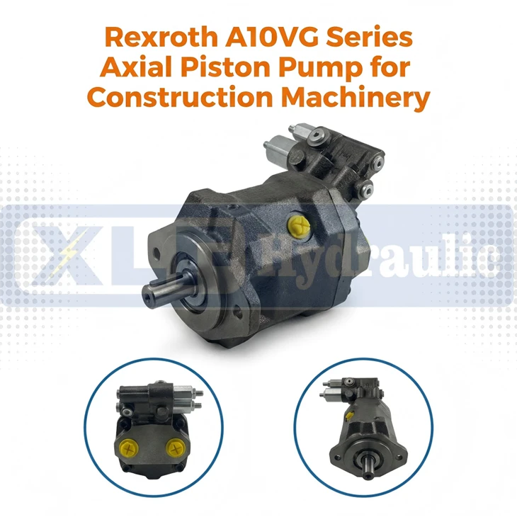
Rexroth A10VG Series Axial Piston Pump For Construction Machinery
Wuhan Xinlaifu Hydraulic Equipment Co., Ltd. is one of the leading manufacturers and suppliers of rexroth a10vg series axial piston pump for construction machinery in China. With abundant experience, we warmly welcome you to buy high quality customized products at competitive price from our factory. Also, OEM&ODM service is available.
Specifications
")
| Type | A10VG Series Axial Piston Variable Pump |
| Brand | XLF Hydraulic |
| Max Output Torque Range | 18 / 28 / 45 / 63 cc/rev |
| Rated Working Pressure | 30 MPa (300 bar) |
| Peak Pressure | Max 35 MPa (350 bar) |
| Mount Flange | SAE Standard Mount Flange |
| Port Size | SAE Standard Hydraulic Ports |
| Built-in Parts | Charge Pump, Dual Relief Valves, Shaft Seals |
| Recommended Oil | ISO VG46 / VG68 Anti-Wear Hydraulic Oil |
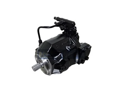
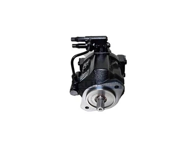
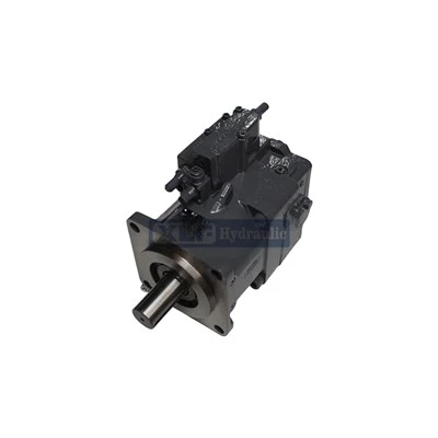
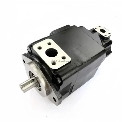
Product Overview
Core Advantages
1. Integrated Through-Drive Structure Design – An Ideal Choice For Closed-Circuit Hydrostatic & Electrified Drive Systems
- Integrated through-drive connecting structure: Custom splined drive shaft and rear through-drive interface design are available. Radial and axial loads from tandem auxiliary pumps are shared by the matched pump/motor assembly on construction machinery;
- Direct integration with hydraulic motors & travel reducer assemblies: The pump can be directly flange-coupled with A6VM, A2FE, A7VO series travel motors without extra intermediate bearings or transition couplings, perfectly matching electro-hydraulic closed-circuit power modules for rotary drilling rigs, road rollers and pavers;
- Compact overall outline: Streamlined swashplate piston core with built-in charge pump greatly shortens overall installation length, making it perfectly suited for construction machinery with narrow engine compartment and limited assembly space;
- Convenient installation & modular combination: Standard SAE heavy-duty mounting flanges and multi-bolt fixed flange layout realize seamless matching with engine power take-off ends and guarantee stable concentricity during high-speed rotation. The modular through-drive design supports multiple pumps tandem assembly, significantly expanding multi-circuit system configuration flexibility for foundation piling and road construction machinery.
2. Rexroth A10VG Series – High Performance Closed-Circuit Axial Piston Variable Pump
- High power density output: Delivers infinitely adjustable stable flow output within a compact cast housing. The matched closed hydraulic circuit features a standard continuous nominal working pressure of 300 bar and intermittent peak pressure up to 350 bar for all displacement sizes (A10VG18 / A10VG28 / A10VG45 / A10VG63);
- Reinforced swashplate piston & robust pump housing assembly: Equipped with optimized heavy-duty swashplate variable mechanism, hardened steel piston assemblies and wear-resistant valve plate structure, it achieves high volumetric efficiency above 95% and outstanding resistance to pressure impact and frequent mechanical vibration during drilling & road compaction operations;
- Stable piston meshing & heavy-duty sealing technology: Precisely ground piston sliding pairs maintain consistent friction matching with automatic wear compensation, retaining stable transmission efficiency under long-duration continuous operation and effectively reducing system power loss. Premium FKM heavy-duty shaft seals are standard equipped to resist mud, dust and water splash penetration;
- Excellent adaptability to harsh operating conditions: Capable of stable continuous operation under rated pressure and sustained heavy variable loads, covering a wide ambient temperature range (-20°C ~ +45°C) and frequent pressure fluctuation cycles. It delivers reliable continuous performance on rotary drilling rigs, piling rigs, crawler loaders and road construction equipment under severe working environments including thick dust, muddy water immersion and strong cyclic vibration.


")
")

Main Specifications
1. General Features
- Swashplate design axial piston variable pump for hydrostatic closed circuit transmission
- Output flow is proportional to drive speed and displacement; infinitely variable flow
- Flow direction changes smoothly when swashplate passes neutral position
- Equipped with two high-pressure relief valves on high-pressure ports for overload protection, also acting as boost valves
- Integrated boost pump serves as feed and control oil pump; maximum boost pressure is limited by built-in relief valve
- Multiple control options: MD, DG, HD, HW, DA, EP, EZ
- Nominal pressure: 300 bar; Peak pressure: 350 bar
2. Hydraulic Fluid & Operating Conditions
2.1 Fluid Standards
Refer to RE 90220 (mineral oil), RE 90221 (environmentally acceptable hydraulic fluids), RE 90223 (HF hydraulic fluids).
Not suitable for HFA, HFB and HFC fluids. Special limits apply to HFD and eco-friendly fluids.
2.2 Viscosity Range
- Optimum operating viscosity: 16 ~ 36 mm²/s
- Minimum viscosity (short-term < 3 min): ≥ 5 mm²/s, max temperature +115 °C
Maximum viscosity (cold start, short-term < 3 min): ≤ 1600 mm²/s
Conditions: p ≤ 30 bar, n ≤ 1000 rpm, t ≥ -40 °C (no load). Reach optimum viscosity within 15 minutes.
2.3 Temperature Range
- FKM shaft seal: -25 °C ~ +115 °C (standard)
- NBR shaft seal: -40 °C ~ +90 °C (for low temperature applications)
- Max local fluid temperature: +115 °C. Bearing area temperature is up to 5 K higher than average case drain temperature.
- Special measures required for operation between -40 °C and -25 °C.
2.4 Fluid Cleanliness & Filtration
- Standard cleanliness class: ISO 4406 20/18/15
- High temperature (90 °C ~ 115 °C): ISO 4406 19/17/14
- Recommended filter element: β₂₀ ≥ 100. β-value must not degrade with rising differential pressure.
3. Pressure Ratings
3.1 System Pressure
| Item | Value |
|---|---|
| Nominal continuous pressure (Port A/B) | 300 bar |
| Peak intermittent pressure (< 1 s) | 350 bar |
| Boost pressure (n = 2000 rpm, HD/HW/EP/EZ) | 18 bar |
| Boost pressure (n = 2000 rpm, DG/DA) | 25 bar |
3.2 Boost Pump Pressure
| Pump Size | Max boost pressure |
|---|---|
| A10VG18 | 25 bar |
| A10VG28 / A10VG45 / A10VG63 | 40 bar |
3.3 Suction Pressure (Boost Pump)
- Normal operation (ν ≤ 30 mm²/s): ≥ 0.8 bar absolute
- Cold start short-term (< 3 min): ≥ 0.5 bar absolute
3.4 Case Drain Pressure (Shaft Seal Protection)
- Continuous average case drain pressure: ≤ 3 bar absolute
- Max continuous case drain pressure (reduced speed): ≤ 6 bar absolute
- Short-term pressure spike (< 0.1 s): max 10 bar absolute
3.5 High-Pressure Relief Valve Setting
| Valve Code | Differential Pressure Range | Standard Setting | Optional Settings |
| ---- | ---- | ---- | ---- | ---- |
| 3 / 5 | 250 ~ 320 bar | 300 bar | 270 bar |
| 4 / 6 | 100 ~ 250 bar | 200 bar | 250 / 230 / 150 / 100 bar |
3.6 Pressure Cut-Off (D)
- Pressure cut-off setting must be 30 bar lower than high-pressure relief valve setting.
- Function: Reduces pump displacement to minimum once set pressure is reached.
3.7 DG Control Pilot Pressure
- Neutral position (Vg = 0): 0 bar
- Max permissible pilot pressure: 40 bar
4. Main Performance Data (Theoretical Values, No Efficiency & Tolerance)
| Parameter | A10VG18 | A10VG28 | A10VG45 | A10VG63 |
|---|---|---|---|---|
| Max displacement Vg max (cm³/rev) | 18 | 28 | 46 | 63 |
| Boost pump displacement @ 20 bar (cm³/rev) | 5.5 | 6.1 | 8.6 | 14.9 |
| Max continuous speed (rpm) | 4000 | 3900 | 3300 | 3000 |
| Restricted max speed (rpm) | 4850 | 4200 | 3550 | 3250 |
| Intermittent max speed (rpm) | 5200 | 4500 | 3800 | 3500 |
| Min operating speed (rpm) | 500 | 500 | 500 | 500 |
| Max flow @ continuous speed & full displacement (l/min) | 72 | 109 | 152 | 189 |
| Max power @ Δp = 300 bar (kW) | 36 | 54.6 | 75.9 | 94.5 |
| Max torque @ Δp = 300 bar (Nm) | 86 | 134 | 220 | 301 |
| Torque @ Δp = 100 bar (Nm) | 28.6 | 44.6 | 73.2 | 100.3 |
| Torsional stiffness, shaft S (Nm/rad) | 20284 | 32143 | 53404 | 78370 |
| Torsional stiffness, shaft T (Nm/rad) | - | - | 73804 | 92368 |
| Moment of inertia JRG (kg·m²) | 0.00093 | 0.0017 | 0.0033 | 0.0056 |
| Max angular acceleration (rad/s²) | 6800 | 5500 | 4000 | 3300 |
| Oil filling capacity (L) | 0.45 | 0.64 | 0.75 | 1.1 |
| Approx. weight (without through drive, kg) | 14 (MD) / 18 (HD) | 25 | 27 | 39 |
5. Drive Shaft Load Ratings
5.1 Max Radial Force (N)
| Distance | A10VG18 | A10VG28 | A10VG45 | A10VG63 |
|---|---|---|---|---|
| a | 1300 | 2500 | 3600 | 5000 |
| b | 1000 | 2000 | 2891 | 4046 |
| c | 880 | 1700 | 2416 | 3398 |
5.2 Max Axial Force (N)
| Size | Max axial force |
|---|---|
| A10VG18 | 973 |
| A10VG28 | 987 |
| A10VG45 | 1500 |
| A10VG63 | 2200 |
5.3 Input & Through-Drive Torque (Nm)
| Item | A10VG18 | A10VG28 | A10VG45 | A10VG63 |
|---|---|---|---|---|
| Theoretical max torque @ 300 bar | 86 | 134 | 220 | 301 |
| Max input torque, shaft S | 192 | 314 | 314 | 602 |
| Max input torque, shaft T | - | - | 602 | 970 |
| Max through-drive torque | 112 | 220 | 314 | 439 |
Shaft Spline Standard (SAE J744 / ANSI B92.1a-1976)
- A10VG18: Shaft S – 7/8 in, 9T 16/32DP
- A10VG28: Shaft S – 1 in, 15T 16/32DP
- A10VG45: Shaft S – 1 in; Shaft T – 1 1/4 in
- A10VG63: Shaft S – 1 1/4 in; Shaft T – 1 3/8 in
6. Control Unit Specifications
6.1 MD – Mechanical Pivot Control (Size 18 only)
- Control lever start: 0°; Max swivel angle: 17.79° (full displacement)
- Actuating torque varies with pressure, speed and displacement
- Optional MDN: Spring centering to neutral position
6.2 HD – Hydraulic Pilot Pressure Control
| Parameter | A10VG18 | A10VG28 | A10VG45 | A10VG63 |
|---|---|---|---|---|
| Start control pressure (Vg = 0, bar) | 6 | 6 | 6 | 6 |
| End control pressure (Vg max, bar) | 15.7 | 16 | 16.7 | 16.7 |
- Y1 / Y2 ports must be vented to tank at neutral position.
6.3 HW – Hydraulic Mechanical Servo Control
- Lever angle range: Start 3°, Max 29°; Mechanical stop ±40°
- Max lever actuating torque: 170 Ncm
- Spring centering as standard; Optional neutral position switch
- Neutral position switch rating: 20 A continuous; 15 A (resistive) / 4 A (inductive) @ 32 V
6.4 DA – Speed-Related Hydraulic Control
Solenoid Electrical Data
| Type | Voltage | Resistance (20 °C) | Power | Min Current | Duty Cycle |
|---|---|---|---|---|---|
| DA1 | 12 V DC (±20%) | 5.5 Ω | 26.2 W | 1.32 A | 100% |
| DA2 | 24 V DC (±20%) | 21.7 Ω | 26.5 W | 0.67 A | 100% |
- Mechanical adjustable lever (DA3): Max operating torque 4 Nm, max rotation 70°
6.5 EP – Electric Proportional Control
Control Current
| Type | Start Current (mA) | End Current (mA) |
| ---- | ---- | ---- | ---- |
| EP3 (12 V DC) | 400 | 1050 ~ 1115 |
| EP4 (24 V DC) | 200 | 525 ~ 560 |
Solenoid Data
- EP3: 12 V DC, 5.5 Ω, Limit current 1.54 A, Dither frequency 100 Hz
- EP4: 24 V DC, 22.7 Ω, Limit current 0.77 A, Dither frequency 100 Hz
6.6 EZ – Electric Two-Point Control
| Type | Voltage | Resistance | Power | Min Current |
|---|---|---|---|---|
| EZ1 | 12 V DC | 5.5 Ω | 26.2 W | 1.32 A |
| EZ2 | 24 V DC | 21.7 Ω | 26.5 W | 0.67 A |
- De-energized = neutral (Vg = 0); Energized = full displacement
6.7 Common Electrical Connector (EP / EZ / DA)
- Connector: DEUTSCH DT04-2P-EP04 (male), DT06-2S-EP04 (female)
- Protection class: IP67, IP69K
- Version P: Without suppressor diode; Version Q: With bidirectional suppressor diode
7. Through-Drive & Combination Pump Data
7.1 Through-Drive Flange & Spline
| Code | Flange | Spline | Applicable Sizes |
|---|---|---|---|
| .01 | SAE J744 82-2 (A) | 5/8 in, 9T 16/32DP | 18 ~ 63 |
| .02 | SAE J744 101-2 (B) | 7/8 in, 13T 16/32DP | 18 ~ 63 |
| .04 | SAE J744 101-2 (B) | 1 in, 15T 16/32DP | 28 ~ 63 |
| .07 | SAE J744 127-2 (C) | 1 1/4 in, 14T 12/24DP | 63 |
7.2 Basic Length (mm)
| Size | N00 (No boost, no through drive) | F00 (With boost, no through drive) |
|---|---|---|
| A10VG18 | 169.4 | 169.4 |
| A10VG28 | 201.7 | 215.3 |
| A10VG45 | 216.8 | 230.5 |
| A10VG63 | 224.5 | 238.2 |
7.3 A10VG + A10VG Tandem Pump Overall Length (mm)
| 1st Pump | A10VG18 | A10VG28 | A10VG45 | A10VG63 |
|---|---|---|---|---|
| A10VG18 | 356.8 | - | - | - |
| A10VG28 | 389.6 | 435.5 | - | - |
| A10VG45 | 404.9 | 450.8 | 466.0 | - |
| A10VG63 | 412.6 | 458.5 | 473.7 | 487.7 |
- Max dynamic acceleration for tandem pump without extra support: ≤ 10 g (98.1 m/s²)
7.4 Mechanical Stroke Limiter Dimensions (mm)
| Size | M1 | M2 | M3 | M4 |
|---|---|---|---|---|
| 18 | 94.9 | 96.9 | 18 | 42.1 |
| 28 | 99 | 99 | 21.5 | 35 |
| 45 | 101.6 | 101.6 | 22.5 | 35.5 |
| 63 | 124 | 124 | 26.5 | 43 |
7.5 Rotary Inch Valve
- Max rotation angle: 90°, lockable at any position
- Max pipe length: 2 m
- Port thread: M14×1.5, Tightening torque: 80 Nm
8. Supplemented Table: Port Thread & Tightening Torque (Missing table restored)
8.1 Port Specifications & Torque (DIN 3852 / SAE J518)
A10VG18
Port Description Thread Specification Tightening Torque Service ports A, B M27×2 330 Nm Case drain / Fill port T1 M18×1.5 140 Nm Case drain port T2 M18×1.5 140 Nm Pressure gauge ports MA, MB M12×1.5 50 Nm Air bleed port R M12×1.5 50 Nm Boost suction port S M26×1.5 230 Nm Control ports X1, X2 M12×1.5 50 Nm Auxiliary circuit port G M14×1.5 80 Nm Control pressure supply PS M12×1.5 50 Nm Remote control ports Y1, Y2 (HD only) M14×1.5 80 Nm
A10VG28 / A10VG45 / A10VG63
| Port Description | Thread Specification | Tightening Torque |
|---|---|---|
| Service ports A, B | SAE J518 3/4 in | Refer to standard |
| Case drain / Fill port T1 | M22×1.5 | 210 Nm |
| Case drain port T2 | M22×1.5 | 210 Nm |
| Pressure gauge ports MA, MB | M12×1.5 | 50 Nm |
| Air bleed port R | M12×1.5 | 50 Nm |
| Boost suction port S | M33×2 | 540 Nm |
| Control ports X1, X2 | M12×1.5 | 50 Nm |
| Auxiliary circuit port G / Fa / Fe | M18×1.5 | 140 Nm |
| Control pressure supply PS | M14×1.5 | 80 Nm |
| Remote control ports Y1, Y2 (HD only) | M14×1.5 | 80 Nm |
| Pilot port Z (DA4/DA8) | M10×1 | 30 Nm |
Note: All values are maximum tightening torque. Do not exceed the specified torque.
9. Coupling Installation Dimensions (mm)
| Size | ød1 | ød2 (min) | ød3 | ød4 | ød5 | x1 | x2 | x3 | x4 |
|---|---|---|---|---|---|---|---|---|---|
| 18 | 30 | 36.1 | 49±0.1 | 101.6 | 65 | 5.9⁺⁰·²₋₀ | 9.5⁰₋₀·₅ | 7 | 8⁺⁰·⁹₋₀·₆ |
| 28 | 35 | 43.4 | 55±0.1 | 101.6 | 72 | 3.9⁺⁰·²₋₀ | 9.5⁰₋₀·₅ | 7 | 8⁺⁰·⁹₋₀·₆ |
| 45 | 40 | 51.4 | 63±0.1 | 101.6 | 80 | 4.3⁺⁰·²₋₀ | 9.5⁰₋₀·₅ | 7 | 8⁺⁰·⁹₋₀·₆ |
| 63 | 40 | 54.4 | 68±0.1 | 127 | - | 7.0⁺⁰·²₋₀ | 12.7⁰₋₀·₅ | - | 8⁺⁰·⁹₋₀·₆ |
10. Filtration Types
- Type S (Standard): Filtration on boost pump suction line. Filter not included.
- Type E (External Supply): For units without integrated boost pump (N00 / K..).
- Type D: Filtration on boost pump pressure line. Not available with DA control for size 28 / 45 / 63.
11. Installation Notes
- Designed exclusively for closed hydrostatic circuits.
- Max suction height (pump above oil level): 800 mm.
- All case drain lines must run below minimum oil level in tank.
- Bleed air from pump and circuit after long standstill or commissioning.
- Max tightening torques for all threads must be observed.
- Wear protective equipment; surface and solenoids may reach high temperature during operation.
Hot Tags: rexroth a10vg series axial piston pump for construction machinery, China rexroth a10vg series axial piston pump for construction machinery manufacturers, suppliers, 11173953 Volvo After Sale Replacement Hydraulic Fan Pumps, cat vq, cat vq series, variable delivery hydraulic pump, Vickers ADU 420 hydraulic spare, Volvo 15020161 Alternative Hydraulic Fan Motor
Next
No InformationYou Might Also Like


Send Inquiry