



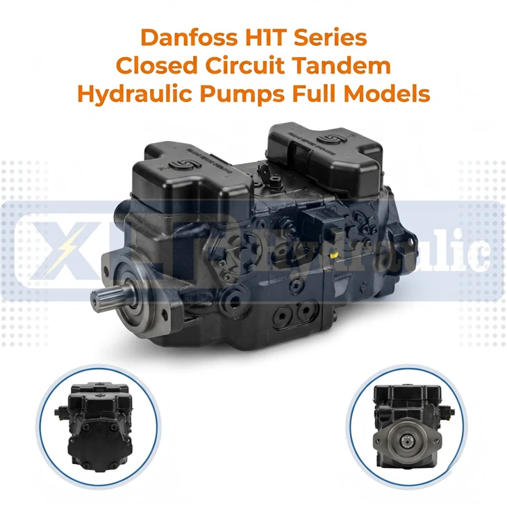
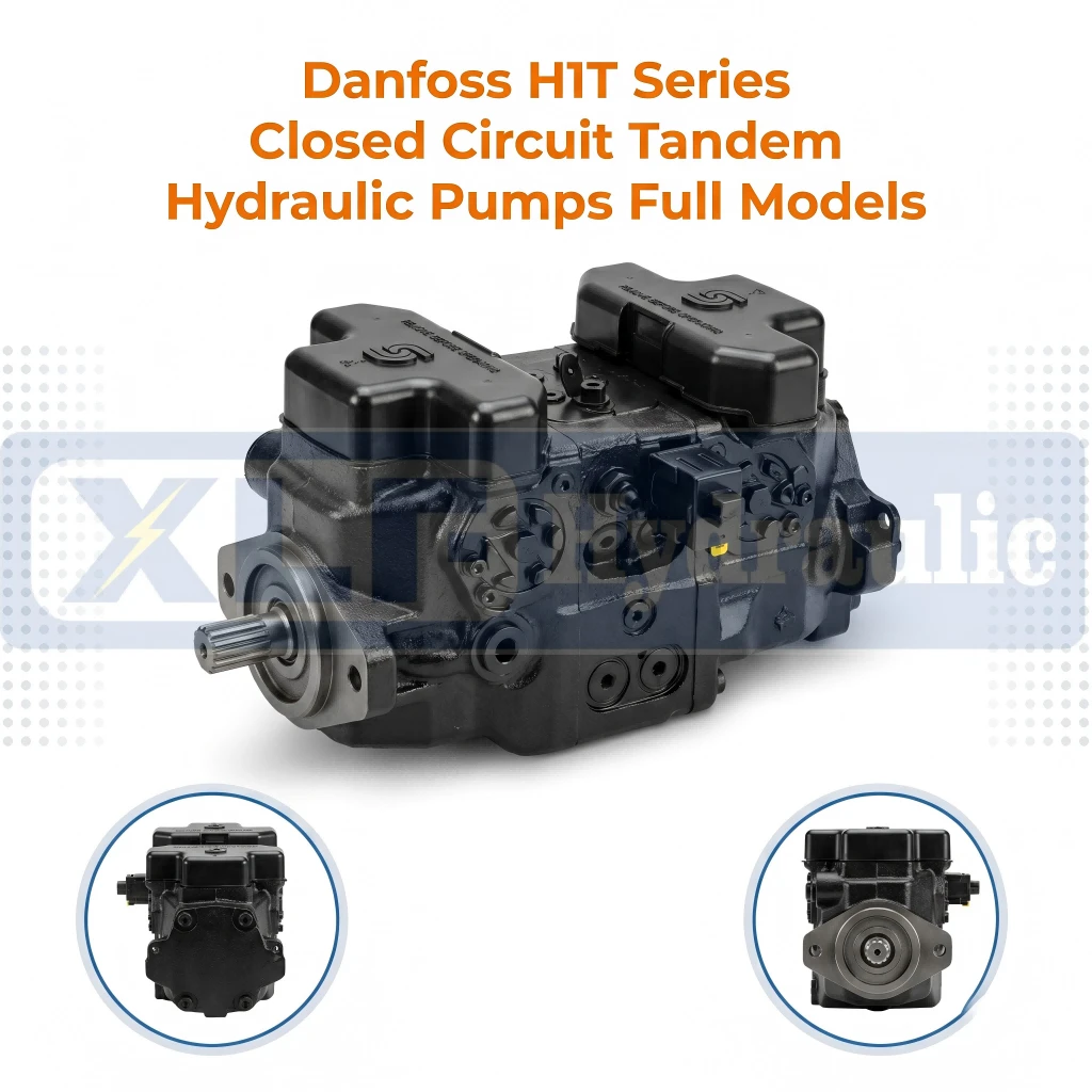
Danfoss H1T Series Closed Circuit Tandem Hydraulic Pumps Full Models
Wuhan Xinlaifu Hydraulic Equipment Co., Ltd. is one of the leading manufacturers and suppliers of danfoss h1t series closed circuit tandem hydraulic pumps full models in China. With abundant experience, we warmly welcome you to buy high quality customized products at competitive price from our factory. Also, OEM&ODM service is available.
Specifications
| Type | HIT Series |
| Brand | XLF Hydraulic |
| Displacement | 45.0/53.8/60.4/68.0 cm³/r |
| Rated Working Pressure | 420/380/420/380 bar |
| Intermittent Peak Pressure | 450/400/450/400 bar |
| Mount Flange | SAE B / SAE C |
| Port Size | SAE O-ring / Split Flange |
| Built-in Parts | 12/24V EDC, dual filtration |
| Recommended Oil | Mineral/synthetic hydraulic oil |
Product Overview
A single hydraulic pump feeds one circuit. A tandem pump-two axial piston units housed end-to-end on a common input shaft-feeds two independent closed circuits simultaneously, sharing one prime mover.
The Danfoss H1T Series takes this tandem architecture and pushes it into heavy-duty hydrostatic territory. Each unit within the tandem pair features a 32° maximum swashplate angle, delivering a 5:1 displacement ratio from maximum to minimum. The 9-piston rotating group, coupled with a high-stiffness valve plate, maintains volumetric efficiency above 94% across the entire displacement range (045 to 190 cc/rev per unit).
Here is the critical distinction for your engineering team: while a single H1 pump is straightforward, the tandem version demands attention to input shaft power calculation-the combined input torque from both units can exceed 800 N·m at peak pressure. Our through-drive shaft design incorporates upgraded bearing spacing to handle this cumulative torsional load, preventing the common failure mode of rear-unit starvation under sustained high-demand cycles.
Core Advantages
2.1 Tandem Through-Drive: Why Mounting Order Matters
The H1T features a through-drive shaft that allows an additional gear pump (for pilot or charge functions) to be mounted directly to the rear cover.
2.2 Charge Pump & Flushing Circuit: Cold-Start Reality Check
Every H1T is equipped with an internal charge pump (supplying make-up oil to both closed loops) and an optional flushing valve for oil cooling.
Most specification sheets list charge pressure at 25–30 bar, but they omit one critical parameter: cold-start viscosity. At ambient temperatures below -10°C, charge pump suction resistance spikes. We pre-set the charge relief valve with a cold-start bypass shim that temporarily raises allowable suction pressure by 5 bar until oil warms up-preventing cavitation damage to the rear-unit pistons during winter morning starts in temperate climates.
2.3 Control Options: Beyond "Electric Proportional"
For synchronized control applications – such as dual-winch drums, twin-track propulsion, or multi-circuit deck machinery – we support control configurations that enable both pump units to respond to a single command signal with consistent stroke behavior. Depending on your system's pilot pressure availability, desired response time, and remote control interface (joystick/PLC), we can tailor the control valve selection and linkage geometry at the factory level. This approach minimizes external plumbing modifications on your vessel and avoids the added cost of slave PLC cards or standalone electronic synchronizers. We evaluate your existing hydraulic schematic and propose the most direct implementation to meet your operational logic – without requiring you to redesign your main control console.
2.4 Pressure Rating & Thermal Management
The H1T series delivers 380 bar continuous differential pressure per unit, with 420 bar peak (intermittent). However, sustained operation above 380 bar on both units simultaneously will raise the case drain oil temperature by approximately 15°C above sump temperature.
Our recommendation: if your system runs both circuits above 350 bar for extended periods, specify the high-flow case drain option (enlarged L-port). This adds 2 kg to the unit weight but reduces case pressure from 4.5 bar to 2.0 bar at full stroke-a modification that directly translates to longer shaft seal life.


Q1: My current system uses two separate single pumps. What do I lose or gain by switching to an H1T tandem?
You gain a shorter axial footprint (about 22% reduction) and eliminate the need for a splitter gearbox. You lose the ability to run one circuit independently if the other fails-both units share the same input shaft. If redundancy is critical, we recommend keeping a single-pump backup, not a tandem.
Q2: The H1T nameplate shows 045 on the front and 055 on the rear. Can I swap their positions to fit my plumbing layout?
Technically yes, but we advise against it unless you recalculate the input shaft torque sequence. Swapping positions changes the torsional stiffness distribution. If you must reverse the layout, we will re-machine the through-drive spline orientation and supply a revised shaft key phase alignment
sheet-please request this modification at the time of ordering, not after delivery.
Q3: How do I set the flushing flow rate correctly for a tandem unit?
The flushing valve is shared between both units on the H1T. Total flushing flow should be set to 10–15% of the combined charge pump flow at maximum engine RPM. A common field mistake is setting it based on only the front unit's displacement. We mark the correct shim thickness on the valve body based on your stated operating RPM range-check that label before adjusting.
Q4: What charge pump pressure do I need if running water-glycol fluid?
Water-glycol has lower lubricity and higher compressibility. We increase the charge pressure setting by 5 bar (factory pre-adjusted) for such fluids. Additionally, we replace the standard nitrile seals in the charge pump with FKM (Viton) equivalents. Please confirm your fluid type at quote stage; we do not stock this variant but can build it within 5 working days.
Q5: Can I mount a gear pump to the through-drive and still fit within a 400 mm mounting envelope?
Yes, but the combined axial length depends on the gear pump flange type. Our standard SAE B-to-B through-drive adapter adds 48 mm. If your envelope is tighter than 400 mm, we offer a short-coupling adapter (28 mm) but it limits the gear pump to a maximum displacement of 30 cc/rev. We will provide a 3D step file of your exact configuration for clearance verification before shipment.
Q6: Why does my tandem unit produce different case drain oil volumes from the front and rear units?
This is normal-and it's a diagnostic indicator. The rear unit typically drains about 8–10% more oil than the front due to the longer internal drain path and additional bearing friction. If the difference exceeds 15%, it suggests the rear unit's charge pressure is too low (likely from suction restriction). Monitor this ratio; we include a case drain comparison log sheet in the manual for preventive maintenance tracking.
Main Specifications
1. Model Code Definition Table
| Code Segment | Code | Description |
|---|---|---|
| Series | H1 | Danfoss H1 Axial Piston Pump Series |
| Structure | T | Integral Tandem Pump |
| Frame Size | 045/053/060/068 | Pump displacement rating |
| Rotation | R | Right-hand (Clockwise) |
| Rotation | L | Left-hand (Counter-clockwise) |
| Version | A | Standard Version A |
| Port Standard | A | ANSI O-ring boss ports |
| Stage Match | N | Rear pump same specification as front pump |
| Electric Control | A2 | 12V Electrical Displacement Control, Deutsch connector |
| Electric Control | A3 | 24V Electrical Displacement Control, Deutsch connector |
| Orifice | C1 | Standard orifice |
| Control Unit | D1 | Standard auxiliary control assembly |
| Control Unit | H4 | MDC Mechanical Displacement Control |
| Mounting Flange | F | SAE B standard flange |
| Mounting Flange | F1 | Reinforced SAE C flange |
| Mounting Structure | H | H-type mounting structure |
| Shaft & Pad | G1 | Standard input spline |
| Shaft & Pad | H3 | With auxiliary mounting pad |
| Auxiliary Pad | NN | No auxiliary pad |
| High Pressure Relief | 35/38 | High pressure relief setting (bar) |
| Charge Pump | N | No built-in charge pump (External charge required) |
| Filtration | P | Remote full flow filtration |
| Filtration | E | Integral filtration |
| Charge Relief | 24 | Charge relief pressure: 24 bar |
| Valve Plate | PN | Standard valve plate, no manual handle |
| Custom Option | NNN | Standard paint, original nameplate, no special customization |
2. Displacement & Flow Rate Table
| Item | Unit | H1T045 | H1T053 | H1T060 | H1T068 |
|---|---|---|---|---|---|
| Max Displacement | cm³/r | 45.0 | 53.8 | 60.4 | 68.0 |
| Max Displacement | in³/r | 2.75 | 3.28 | 3.69 | 4.15 |
| Flow @ Rated Speed | L/min | 153 | 183 | 210 | 238 |
| Flow @ Rated Speed | US gal/min | 40 | 48 | 55.5 | 62.8 |
| Theoretical Torque | N·m/bar | 0.8 | 0.9 | 0.96 | 1.08 |
3. Rotational Speed Table
| Item | Unit | H1T045 / H1T053 | H1T060 / H1T068 |
|---|---|---|---|
| Min Operating Speed (External Charge) | rpm | 500 | 500 |
| Rated Continuous Speed | rpm | 3400 | 3500 |
| Max Intermittent Speed | rpm | 3500 | 4000 |
4. Pressure Rating Table
表格
| Item | Unit | H1T045 | H1T053 | H1T060 | H1T068 |
|---|---|---|---|---|---|
| Max Continuous Working Pressure | bar | 420 | 380 | 420 | 380 |
| Max Continuous Working Pressure | psi | 6092 | 5511 | 6090 | 5510 |
| Max Peak Pressure | bar | 450 | 400 | 450 | 400 |
| Max Peak Pressure | psi | 6527 | 5802 | 6525 | 5800 |
| Low Side Pressure Range | bar | 10 ~ 45 | 10 ~ 45 | 10 ~ 45 | 10 ~ 45 |
| Low Side Pressure Range | psi | 145 ~ 653 | 145 ~ 650 | 145 ~ 650 | 145 ~ 650 |
| EDC Control Pressure | bar | 21.5 ~ 40 | 21.5 ~ 40 | 18.5 ~ 40 | 18.5 ~ 40 |
| Rated Case Pressure | bar | 3.0 | 3.0 | 3.0 | 3.0 |
| Max Case Pressure | bar | 5.0 | 5.0 | 5.0 | 5.0 |
| Max Shaft Seal External Pressure | bar | 0.4 | 0.4 | 0.4 | 0.4 |
General Charge Pressure: Min 14.5 bar (without CCO valve); Min 18 bar (with CCO valve); Max 34 bar (All models)
5. Physical Dimension & Weight Table
| Item | Unit | H1T045 / H1T053 | H1T060 / H1T068 |
|---|---|---|---|
| Net Weight (No charge pump) | kg | 65 | 96.2 |
| Net Weight (No charge pump) | lb | 143 | 212 |
| Case Volume | L | 2.3 | 4.2 |
| Case Volume | US gal | 0.61 | 1.1 |
| Rotational Inertia | kg·m² | 0.0077 | 0.0143 |
| Main Mounting Flange | - | SAE B (ISO 3019-1 101-2) | SAE C (ISO 3019-1 127-4) |
| Main Port Type | - | SAE O-ring boss thread | Split flange (M12×1.75) |
6. Hydraulic Fluid Requirements Table
表格
| Category | Specification |
|---|---|
| Recommended Viscosity | 12 ~ 80 mm²/s |
| Min Continuous Viscosity | 7 mm²/s |
| Min Intermittent Viscosity (<1min) | 5 mm²/s |
| Extreme Viscosity | 1600 mm²/s |
| Recommended Oil Temperature | 60 ~ 85 ℃ |
| Normal Operating Temperature | -40 ℃ ~ 104 ℃ |
| Intermittent Max Temperature (<3min) | 115 ℃ |
| Compatible Fluids | Mineral hydraulic oil, Water-glycol fluid, Synthetic hydraulic fluid |
7. Shaft Load & Installation Table
| Item | Unit | H1T045 / H1T053 | H1T060 / H1T068 |
|---|---|---|---|
| Max External Radial Moment | N·m | 104 | 104 |
| Max External Radial Moment | lbf·in | 920 | 920 |
| Rated Flange Moment | N·m | 2020 | 2190 |
| Shock Flange Moment | N·m | 4110 | 6560 |
| Installation Instruction | - | Mountable at any angle. Pump case must be fully filled with fluid during operation. |
8. Full Model Configuration Comparison Table
| No. | Full Model Code | Frame & Rotation | Electric Control | HP Relief Pressure | Charge Relief | Filtration | Control Assembly | Flange & Shaft | Charge Pump |
|---|---|---|---|---|---|---|---|---|---|
| 1 | H1-T-045-R-A-A-N-A3-N-C1-D1-F-G1-NN-35-35-35-35-N-P-24-PN-NNN-NNN | H1T045 / RH | 24V EDC(A3) | 35 bar | 24 bar | Remote(P) | C1+D1 | SAE B, Standard spline, No aux pad | None |
| 2 | H1-T-053-L-A-A-N-A2-N-D1-D1-F-G1-H3-38-38-38-38-N-P-24-PN-NNN-NNN | H1T053 / LH | 12V EDC(A2) | 38 bar | 24 bar | Remote(P) | Dual D1 | SAE B, Standard spline, Aux pad(H3) | None |
| 3 | H1-T-060-R-A-A-N-A3-N-C1-H4-H-F1-H3-38-38-38-38-N-E-24-PN-NNN-NNN | H1T060 / RH | 24V EDC(A3) | 38 bar | 24 bar | Integral(E) | C1+H4 | Reinforced SAE C, H-type, Aux pad(H3) | None |
| 4 | H1-T-068-R-A-A-N-A3-N-C1-H4-H-F1-H3-38-38-38-38-N-E-24-PN-NNN-NNN | H1T068 / RH | 24V EDC(A3) | 38 bar | 24 bar | Integral(E) | C1+H4 | Reinforced SAE C, H-type, Aux pad(H3) | None |
Hot Tags: danfoss h1t series closed circuit tandem hydraulic pumps full models, China danfoss h1t series closed circuit tandem hydraulic pumps full models manufacturers, suppliers, duplex piston pump, gpm 2fc004ft06 pump, komatsu pc series, piston displacement pump, simple piston pump, variable speed gear pump
You Might Also Like


Send Inquiry